Draft:Synchronous machine
| Submission declined on 9 July 2024 by Robert McClenon (talk). Thank you for your submission, but the subject of this article already exists in Wikipedia. You can find it and improve it at Synchronous motor instead. The proposed article does not have sufficient content to require an article of its own, but it could be merged into the existing article at Synchronous motor. Since anyone can edit Wikipedia, you are welcome to add that information yourself. Thank you.
Where to get help
How to improve a draft
You can also browse Wikipedia:Featured articles and Wikipedia:Good articles to find examples of Wikipedia's best writing on topics similar to your proposed article. Improving your odds of a speedy review To improve your odds of a faster review, tag your draft with relevant WikiProject tags using the button below. This will let reviewers know a new draft has been submitted in their area of interest. For instance, if you wrote about a female astronomer, you would want to add the Biography, Astronomy, and Women scientists tags. Editor resources
|
 Comment: This draft appears to largely overlap with synchronous motor. It contains considerable new information that should be added to the existing article. It does not appear that a separate article is needed. This draft has information that is not in the article and should be added to the article. The article has information that is not in this draft. Please compare and combine the draft and the article.You may ask for advice about comparing and combining a draft and an article at the Teahouse. Robert McClenon (talk) 14:25, 9 July 2024 (UTC)
A synchronous machine is a rotating electrical machine in which the rotor (also: rotor) synchronous with the rotating field of the stator (also: stator).[1] Synchronous machines are often designed as three-phase machines, i.e. as three-phase synchronous machines. The synchronous machine bears its name because of the operating characteristic that its rotor rotates synchronously with the rotating field specified by the mains frequency. This distinguishes synchronous machines from asynchronous machines, whose rotor lags the rotating field in motor operation and leads it in generator operation. A further distinguishing feature is that, in contrast to asynchronous machines, an additional excitation field is required for the operation of synchronous machines.[2]
In principle, every synchronous machine can be operated as an electric motor and an electric generator.
Synchronous generators are used in the energy industry to provide electrical energy over a wide power range. They simultaneously supply active power and reactive power (generally from inductive cos phi 0.8 to capacitive cos phi 0.9 or as a so-called phase shifter, which only supplies reactive power) and meet the requirements of the transmission system operator for the electricity grid. The reactive power behavior is influenced by the excitation current.[3] The synchronous generator is connected to the grid by the synchronization process. In generator mode, the machine generally runs at a relatively constant speed, depending on the mains frequency.
Synchronous motors are widely used as drive machines in industry, for example as drives for ships and trains or for pumps and compressors. In contrast to generators, synchronous motors often have to be variable in speed. In order to be able to control the speed of a synchronous motor continuously, power electronics such as a frequency converter is used.[4] A rotary encoder (line encoder, resolver) constantly records the change in rotor position during operation. The control electronics use this to determine the actual speed. Under load, the rotor of the synchronous motor follows the rotating field at a load-dependent pole wheel angle. In generator mode, the pole wheel angle is positive in the direction of rotation, i.e. it leads.

History
As a forerunner of the three-phase synchronous machine, the single-phase alternating current generator was used from the middle of the 19th century to supply lighting systems. In 1887, Friedrich August Haselwander and the American Charles Schenk Bradley independently developed the three-phase synchronous generator. During the course of these developments, the designs of the salient-pole and full-pole machine emerged. A co-founder of Brown, Boveri AG, Charles E. L. Brown, is regarded as the inventor of the roller rotor, with the exciter winding distributed around the circumference in grooves.[5]
The further development of the synchronous machine was closely linked to the expansion of the electrical power supply as part of electrification and the need for ever more powerful generators. Single-pole or salient-pole machines were developed first, as these were suitable for generating electricity with the slow-running piston steam engine as the prime mover. When the steam turbines replaced the piston steam engines, the high-speed cylindrical solid-pole rotors were used.The synchronous machine is of great importance in electricity generation. In large power plants, such as coal-fired power plant or nuclear power plants and in gas turbine power plants of all sizes, synchronous generators are used almost exclusively.[6]
Irrespective of this, synchronous machines have always been used in industry when a constant drive speed or phase shifter operation was required.[7][8]
Types of synchronous machines
A distinction is made between the following types of synchronous machines[9]
- Full-pole machines (turbogenerators) - (high speeds)
- salient-pole machines - (low to medium speeds)
- claw-pole machines - (high speeds at low power)
- Synchronous motors (low to high speeds)
Versions
Depending on the application, synchronous machines are manufactured as external pole machines or internal pole machines. What both types of machine have in common is that, like all three-phase machines, they have a rotor and a stator. In each case, an excitation device is required to operate the machines.[10]


Internal pole machine
Stator
The outer fixed part of the synchronous machine is the stator and is designed accordingly depending on the type. In turbo generators, for example, it consists of the stator housing, the laminated core with the inserted stator winding (with twisted copper part conductors, the Roebel bars).[11]
Rotor
Other names for the rotor are rotor, pole wheel and more rarely inductor. Depending on the application, salient-pole rotors are found in internal-pole machines, e.g. in hydroelectric power plants or solid-pole rotors in gas and steam turbine power plants; occasionally also salient-pole rotors up to approx. 60 MW.[11]
The full-pole rotor in turbogenerators is also referred to as a roller rotor or full-pole rotor. It is rotationally symmetrical and is manufactured from a highly tempered forged part in view of its very high mechanical stresses and is subject to very high quality and testing procedures.[10] The rotor and the associated stator plate pack are cooled by one or more fan wheels.In contrast, the salient-pole rotor in salient-pole machines has pronounced pole shoes and legs, which is why they have a large diameter depending on the number of pole pairs. The excitation winding is wound on the rotor legs.
Excitation
There are basically three types of excitation systems for synchronous machines, permanent magnet excitation for smaller synchronous machines, the static excitation and brushless excitation.[12]
- If it is a permanent magnet synchronous machine (PSM), the rotor carries permanent magnets for excitation. This is becoming increasingly important. The hybrid synchronous machine (HSM), on the other hand, combines the effect of electromagnetic reluctance and the effect of permanent magnets to generate torque.
- Static excitation refers to the supply of the complete excitation power, which is taken from the power plant's own requirements and fed to the synchronous generator via the generator exciter cabinet. In this case, the rotor is fitted with two slip rings. For hydrogen-cooled synchronous generators, a special slip ring shaft with a separate bearing with a special hydrogen-tight bushing is required. The energy is transmitted to the slip rings by means of a so-called ventilated brush device with holders for the special carbon brushes, which can be routinely replaced during the standstill inspection, but also individually during operation.
- The brushless excitation consists of an external pole synchronous generator coupled to the generator rotor. The three-phase current generated (there are also versions with five-phase and more alternating current) on its rotor is rectified to a direct current as excitation current with the aid of a rotating rectifier set (rotating rectifiers, so-called RG sets). The current is fed into the axial bores of the shaft. Advantage: low service and excitation energy is generated directly from the rotational energy of the generator set. A small amount of electrical energy is taken from the power plant's own requirements, so that all associated components can be designed in a technically simpler and therefore cheaper way.
Damper winding (damper cage)
Larger synchronous machines have a damper winding (damper cage). It has an effect on the operating behavior of synchronous machines. In full-pole machines, the damper winding is located in the slots of the exciter winding or between these slots in separate damper slots. In salient-pole machines, the damper winding is located in separate damper slots in the pole shoes. The damper winding in full-pole machines is similar in principle to the structure of the squirrel-cage rotor of a Asynchronous machine.[13] However, depending on the design, synchronous machines can have inherent damping without a damper winding, which also has an effect on operation.
The most important task of the damper winding of synchronous machines is to dampen mechanical oscillating torques. Oscillating torques occur due to asynchronous operation, machines coupled to the synchronous machine with periodic torque (e.g. combustion engines as prime movers or piston compressors as driven machines) and load surges. In unbalanced operation (unbalanced load) and in extreme cases with single-phase operation, a inverse rotating field occurs, which is also damped. Without damping, the inverse rotating field would result in high losses.The damping of the inverse fields is particularly important for generator operation. Inverse fields cause a current in the damper winding whose frequency is twice as high as the mains frequency. The damper winding is designed with low resistance in order to keep losses to a minimum.[14]
In motor operation, oscillating torques in particular must be damped. When loaded with a constant load torque, there is a balance between the torque demanded by the load and the torque supplied by the machine under a constant pole wheel angle (see also Spring model of the pole wheel angle of a synchronous machine). A sudden increase in the load torque (load surge) delays the rotation of the rotor beyond the pole wheel angle due to the mass moment of inertia of the rotor. The load torque is now smaller than the motor torque and this in turn causes an acceleration due to the mass moment of inertia until the pole wheel angle is too small. This oscillation is repeated with ever decreasing amplitude until equilibrium is reached again. The relative movement between the stator rotating field and the rotor generates a torque according to the asynchronous machine principle, which counteracts the oscillating movements. Solid parts of the rotor also have a similar effect, such as the solid rotor ball of the full-pole machine or the solid pole shoes of the salient-pole machine. This means that a certain amount of damping can also take place without a damper winding. In addition to damping oscillating torques, the damper winding can also be used for self-starting according to the principle of the asynchronous motor with squirrel-cage rotor.[13]
Design of the windings
The stator and exciter windings are designed according to their specified rated power. The possible permissible short-circuit current is also taken into account and compliance with the technical specifications of DIN EN IEC 60034 is ensured.[15]
The resulting copper cross-sections of the windings together with the thickness of the winding insulation thus determine the required slot cross-sections. The heating of the windings caused by the current requires the use of certain insulating materials in order not to exceed the excess temperature limit. The specification for larger synchronous machines in the 50 Hz sector is insulation material class "F" (155 °C) with utilization to "B" (130 °C), so that sufficient thermal reserve is available (in the 60 Hz sector there is no restriction on utilization).[15]

External pole machine
Two fundamentally different designs of synchronous machines are called "external pole machines":
- In the stator of the external pole machine there are pronounced pole shoes and legs which carry the excitation winding. The three-strand rotor winding is located on the rotor, also called the armature in the case of the external pole machine. The ends of the rotor winding are led out via slip rings. Carbon brushes reduce the power supplied in generator mode or supply the required power in motor mode. This design is not suitable for machines with a high rated power, as the currents increase as a function of the power. This is associated with an increase in losses on the slip ring assembly and the need to make the slip ring assembly larger in order to carry the currents. Internal pole machines are used for high outputs.
- In these, also known as external rotor machines, the bell-shaped rotor carries the energizing permanent magnets on the inside. The stator, usually with pronounced poles, carries the three-strand winding, usually in a delta but also in a star connection. This design has the advantage of relatively high torque and relatively low speeds and is usually used for machines with low rated power. For example, it is used for low-speed model motors[16], axial fans, hard disk drives, wheel hub motors, servo drives[17] or even small wind generators, but the external rotor machine can also be found in the two to (low) three-digit kW range as a drive for electric cars [1].
Cooling
The stator winding and the rotor winding of synchronous machines heat up during operation due to the currents that occur. In addition to these so-called copper losses, there are the iron losses of the stator laminations that occur during remagnetization. While the copper losses depend on the load, the iron losses are almost independent of the load.[15]
In permanent magnet synchronous machines, the excitation magnets also heat up due to eddy currents and thermal radiation. Permanent magnets made of the material neodymium-iron-boron are usually used here, which lose remanence temporarily or permanently from 80 °C, depending on the material composition. Cooling the rotor is therefore very important. External rotors are superior to internal rotor machines in this respect, but it is comparatively more difficult to dissipate the waste heat from the wound stator, which is why cooling air openings are usually provided in the rotor.[7]
Die Verlustwärme wird je nach Maschinenleistung und damit einhergehender Bauform durch unterschiedliche Kühlmethoden abgeführt. Es gibt offene und geschlossene, eigen- und fremdbelüftete, direkte und indirekte Kühlmethoden. Verschiedene Kühlmedien wie Luft, Wasserstoff oder Wasser können dabei zur Anwendung kommen.[18]
Indirect Cooling Methods
Hydrogen-cooled Synchronous Generators
In the power range from approximately 300 MWel to 500 MWel, hydrogen-cooled generators are used. The specific heat capacity of hydrogen is significantly higher compared to air, allowing the generator dimensions to be kept small despite higher power requirements. Therefore, this cooling method is referred to as cooling gas instead of cooling air. However, this cooling method requires significantly higher technical effort. The stator housing must be designed to be pressure-resistant (approximately 4 bar) and explosion protection must be applied. Special auxiliary systems for, e.g., sealing oil and hydrogen, are necessary. The rotor impellers circulate the hydrogen inside (primary circuit), and the heat loss is conducted to the external cooling system via hydrogen/water heat exchanger installed in the stator housing.[19]
Direct Cooling Methods
Water-cooled Synchronous Generators
This cooling method is found in the highest power generators (greater than 500 MWel) and consists of a combination of water and hydrogen cooling. The generator is also hydrogen-cooled here, but primarily only the rotor winding is cooled. The stator winding is directly cooled with demineralized cooling water (deionized water). A special stator winding is designed with hollow Roebel bars and an inner stainless steel lining.
There are also designs with water-cooled rotor windings, which were not further used due to their complexity.
Overpressure air-cooled synchronous generators
To reduce the high technical requirements and associated cost savings for hydrogen-cooled generators, Siemens Energy has developed a further cooling variant. The stator winding is designed in the same way as the high-power generators, i.e. directly cooled.[20]
Depending on the power output, the interior of the generator is operated with an adjustable air overpressure (up to 1 bar). The heat loss is dissipated by redundant air/water heat exchangers.In the past, prototypes with superconducting rotor windings have also been tested in order to reduce losses and thus save winding copper.[21]
Application
The main applications of synchronous machines are the three-phase generators in power plants. Almost all conventional electrical energy production is carried out with synchronous generators. In thermal power stations, full-pole machines with outputs of up to almost 2000 MVA and output voltages of 21 to 27 kV are used. The Siemens plant in Mülheim built the world's largest generator for the Finnish [Olkiluoto]] nuclear power plant. It has an measured apparent power of 1992 MVA at cos phi 0.9.[22]
These generators, with their fast-rotating turbo rotors, are called turbosets in conjunction with the turbines. The low-speed salient-pole machines in hydropower plants are called hydropower or hydrogen generators and deliver outputs of up to 1000 MVA at a maximum stator voltage of 25 kV. Generators with a lower output of 10 kVA to 10 MVA are used in small power plants and diesel generators and are usually also designed as salient-pole machines. Synchronous generators for wind turbines are currently manufactured with an output of up to 8 MW.[23] They are also used to supply local grids. The synchronous generator is also used to provide electrical energy for operating rail vehicles and ship propulsion and will probably also be used in road vehicles in the future. A special type of salient-pole machine is the claw-pole machine, which is mainly used as a vehicle alternator (generator).
Railway Power Generators
A special case is the generators for producing railway power. Due to the single-phase voltage with approximately 16.7 Hz, these generators are designed as single-phase alternating current synchronous machines. Their nominal frequency was previously one-third of 50 Hz (162/3 Hz) and was later changed to 16.7 Hz for technical reasons.[24]
The magnetic flux within these generators is three times greater than the flux in 50 Hz machines with the same output. Traction current generators therefore require correspondingly larger iron cross-sections. For this reason, they are significantly larger than comparable 50 Hz generators. In addition, there is a pulsating torque on the drive that circulates at twice the mains frequency. This pulsation also affects the foundations of the machine; the generator is therefore mounted on springs. An elastic coupling is used between the drive and generator for the same reason. Traction current generators are usually driven by electric motors from the power grid (the combination is called a converter), the facility is called a converter plant.[24]
Nowadays, traction current is also generated from the three-phase grid in converter plants with power electronics.
-
 Leg pole generators of the Hoover Dam
 -
 Powerhouse of the Walchensee power plant; AEG salient-pole generators on the right, Francis turbines on the left
 -
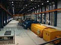 Modern turbogenerator (yellow cylindrical unit in the center); 800 MW; powerhouse of Schwarze Pumpe power plant
 -
 Three-phase synchronous motor during assembly
 -
 French locomotive series BB 26000 with three-phase synchronous motors
 -
 Rotor of an electrically excited ring synchronous generator of an Enercon wind turbine


High-power three-phase synchronous motors are used to drive blowers, pumps and compressors, and sometimes as rail drives (SNCF BB 26000,[25] TGV, AGV). With the possibility of controlling the speed via frequency converters, the synchronous motor replaced large direct current machines, but also gas turbines for driving turbo compressors. In the small and medium power range, motors with permanent magnets are used for auxiliary and vehicle drives.[7] One application in the field of automation technology is the combination of two synchronous machines. This combination serves as a sensor and actuator for transmitting the angular positions of the rotor and is also referred to as a rotary encoder or rotary signal transformer. In addition to synchronous machines, other types of machine are also used as rotary encoders. An example of the use of a small synchronous machine outside of energy technology is the synchronous motor in the Hammond organ.
Economic aspects
The economic efficiency of a machine is determined, among other things, by the purchase and operating costs as well as the efficiency. The efficiency of the synchronous machine (approx. 95...99 % depending on the size and the required excitation power) is generally higher than that of the asynchronous machine due to the synchronous current and voltage phases. Large synchronous machines such as turbo generators are therefore among the most efficient energy converters. Due to the excitation device of the synchronous machine, the design of the synchronous machine is more complex than that of the asynchronous machine and therefore also more expensive. The cost of the control electronics is similar to that of the asynchronous machine.[26]
Permanent-magnet synchronous machines achieve even higher efficiencies as they do not need to be supplied with excitation power. With the same output and greater power density, the mass of the machines is reduced or the size is reduced. Generators of this type achieve an efficiency of over 98 % in wind turbines and are therefore more efficient than machines of the same size with electrical excitation. Permanent magnet excitation is only used for small to medium-sized machines. The costs for the magnets become more and more significant with larger machines, so that the economic efficiency is no longer given compared to machines with electromagnetic excitation. The complicated assembly of the magnets is also a major disadvantage.[27][28] As of 2023, the largest permanent-magnet synchronous machines are used in wind turbines and achieve a rated power of up to 6 MW in on-shore systems[29] and up to 18 MW in off-shore turbines.
Manufacturer
The following manufacturers are a selection with some of their products in the field of synchronous machines:[30]
- ABB - Asea Brown Boveri
- AEM - Anhaltisches Elektromotorenwerk Dessau - synchronous generators and motors
- Brush
- General Electric Power
- Leroy-Somer - Drive technology and generators
- Lloyd Dynamowerke - synchronous generators and motors, high-voltage synchronous generators and motors, marine propulsion systems
- Loher GmbH|Loher]] - Permanently excited synchronous motors and generators
- KSB SE/REEL - synchronous reluctance motors without permanent magnets
- Schorch Werke, Mönchengladbach (ATB AG) - drive technology and high-voltage synchronous motors
- Siemens Energy] - synchronous generators and motors, railroad motors, permanent magnet servo motors
- VA Tech Elin EBG]] - synchronous generators and motors, synchronous traction motors
- VEM Group - synchronous generators, high-voltage synchronous motors, marine drives
Advantages and disadvantages
Advantages:
- very high efficiency
- low mass moment of inertia
- low maintenance (if excitation without slip rings)
- Speed independent of load
- Relatively large air gap possible
- controllable reactive power generation (with excitation current supply)
- Suitable for phase shifter operation (pure reactive power generation)
Disadvantages:
- excitation power always required if not permanently excited or expensive material for permanent magnets
- High control effort (modern electronics)
- no self-starting (without major damping)
Operating modes


Generator operation
In order for the synchronous machine to operate as an electrical generator, i.e. as a three-phase synchronous generator, an excitation field is required in the rotor circuit (internal pole machine). This means that an dc-excited rotor winding (rotor (excitation) winding) or a permanent magnet, a magnetic field (excitation field) must be generated that induces a stator voltage induced in the stator winding strands. The strands of the stator winding are linked to form a star. A three-phase alternating voltage is obtained at the generator terminals (L1, L2, L3), i.e. three alternating voltages shifted in phase by 120°. The stator phase voltage (also known as the terminal voltage) can be calculated as follows, knowing the synchronous reactance , the stator current and the pole wheel voltage :


When using an excitation winding, excitation power must be supplied to generate the excitation field. There are various excitation systems, for example the static excitation device or the brushless excitation device. In order to avoid damage to the generator in the event of sudden load shedding To prevent damage to the generator in the event of sudden load shedding, a separate de-excitation circuit is provided for larger machines.
The speed of the drive machine determines the speed of the generator and thus the number of pole pairs through direct mechanical coupling. If the speed is 3000 rpm, the generator has two poles (number of pole pairs 1) in order to correspond to the 50 Hz mains frequency; at 1500 rpm, the generator has four poles (number of pole pairs 2). For higher-speed drive machines, a so-called load gearbox is provided between the drive machine and the generator.
The supplied mechanical and output electrical active power is calculated as follows
- , with the angular frequency (f corresponds to speed ) and the torque supplied by the drive machine
- , with the string voltage , the string current and the power factor


This equation is valid for star-connected and delta-connected machines. If referenced, non-absolute values are used for the calculation, the 3 must be removed.
If the losses are neglected, applies. However, Hysteresis and Stromwärmeverluste as well as friction losses occur in the real generator. If the electrical power dissipated is divided by the mechanical power supplied, the efficiency of the machine is obtained, which is always less than 1, i.e. less than 100%.

The flux linkage forms the relationship between Rotor speed and induced pole wheel voltage .


The flux linkage can be determined in an open-circuit test. To do this, the machine is driven at a known angular velocity and the voltage across one of the phases to the neutral conductor is measured (in the simplified single-phase equivalent circuit diagram, this corresponds to the voltage ). If a twelve-pole () machine is driven with and a phase-to-star-point voltage of is measured, this results in a flux linkage of .


Summary of the mode of operation:
- Generator is idling at rated speed.
- The generator is connected to the grid when all synchronization conditions are established.
- The prime mover supplies mechanical power (increase in torque) (e.g. fuel increase in gas turbines)
- Since the grid specifies the frequency and thus the speed, the generator produces electrical energy; a three-phase alternating current flows (stator current ).
- The stator current causes a differential voltage at the synchronous reactance (inductive reactance of the stator winding; ohmic resistance neglected).
- Due to the voltage drop at , a stator current-dependent pole wheel angle is formed, which is always positive in the direction of rotation during generator operation.
- As a result, the pole wheel voltage shifts to the fixed mains voltage (compared to idling) with the angle of the pole wheel in the direction of rotation.
- At constant torques, an equilibrium and a constant pole wheel angle are formed and the synchronous speed is maintained; fluctuating loads in the grid can disturb this equilibrium.


The stator voltage is load-dependent. With a constant excitation current and constant speed, different characteristic curves result for capacitive, inductive and resistive loads. A capacitive load results in a voltage boost, a resistive load results in a weak drop and an inductive load results in a sharp drop in the stator voltage. In order to keep the stator voltage constant, the excitation current must therefore be regulated according to the load. The regulation characteristic shows how the excitation current must be regulated according to the different loads: inductive load requires a strong increase in the excitation current, resistive load a weak one. In order to counteract the strong increase in the stator voltage with capacitive loads, the excitation current must be strongly reduced.[3] The excitation current is kept constant in generators in large power plants. Here, the voltage is regulated by means of tap changers of the downstream generator transformers.


Motor operation
As with generator operation, motor operation also requires an energized rotor winding (excitation winding) or a permanent magnet to generate an excitation field. In addition, electrical energy must be supplied via the stator windings so that the three-phase synchronous motor can deliver a torque to the shaft. The electrical power consumed is calculated as follows:
- , with the linking factor , the stator voltage , the stator current and the power factor


The mechanical power delivered corresponds to the electrical power consumed, minus the power loss component , which consists of copper and iron losses as well as friction losses. , with the angular frequency (speed in revolutions per second) and the torque demanded by the driven machine


The ratio of mechanical power output to electrical power input expresses the efficiency of the machine.
The simplified equivalent circuit diagram of the synchronous machine can be found in the section Generator operation. In the article Three-phase machine, the drive principle is described by a rotating field, which applies to both synchronous and asynchronous motors.
Summary of the mode of operation:
- The synchronous machine is idling on the fixed network.
- A load is applied to the motor shaft by a driven machine.
- The motor would reduce its speed, but the motor now consumes electrical power and the stator current increases.
- There is now a motor torque that counteracts the load torque.
- The stator current causes a differential voltage at the synchronous reactance (inductive reactance of the stator winding; ohmic resistance neglected).
- Due to the voltage drop at , a stator current-dependent pole wheel angle is formed, which acts against the direction of rotation during motor operation.
- As a result, the pole wheel voltage shifts to the fixed mains voltage (compared to idling → idling pointer image see generator operation) with the angle of the pole wheel against the direction of rotation.
- The motor continues to run at synchronous speed; there is no slip as with an asynchronous motor.
Synchronous motors with low damping do not start alone. The rotor of a synchronous motor usually has too large a mass moment of inertia to follow the rotating field from standstill. For this reason, the motor speed must be brought close to the rotating field speed without load. The excitation is then switched on and the rotor of the motor is pulled into synchronous operation. The motor can then be loaded. Various methods are available for starting:
Start motor A coupled starter motor (also called starting motor) brings the speed of the synchronous motor close to the speed of the rotating field. Once synchronization is complete, the starter motor is uncoupled. Asynchronous starting through additional damper cage in the rotor circuit The damper cage allows the synchronous motor to start up according to the principle of the Asynchronous machine. If the motor speed reaches the rotating field speed after the excitation is switched on, the damper cage loses its effect as a starting cage and the motor continues to run as a synchronous machine. During start-up, the excitation winding is usually short-circuited via a resistor in order to avoid the induction of high voltages and to increase the start-up torque. Frequency start-up The frequency of the supply voltage is continuously increased from zero to the rated frequency or the resulting rated rotating field speed. An obsolete method for this is frequency conversion by means of an upstream asynchronous generator. The frequency of the generator's output voltage is increased via the supplied speed or its slip. Today, power electronic converters are used for frequency starting. Load starting is also possible with this method.[8]

Phase shifter operation
Phase-shift operation is an operating mode of synchronous machines synchronized to the grid in which almost exclusively reactive power is drawn from the grid or fed into the grid. The synchronous machine is operated in mechanical no-load operation; the comparatively low active power that is nevertheless consumed is used to cover losses such as thermal losses in the electrical windings or losses due to mechanical friction in the bearings.[8]
By increasing or decreasing the excitation current, the amount of reactive power supplied to or taken from the grid is influenced. When overexcited, capacitive reactive power is absorbed (behavior like a capacitor) and when underexcited, the synchronous machine absorbs inductive reactive power (behavior like a coil). The output of inductive reactive power corresponds to the consumption of capacitive reactive power and vice versa, according to the Designation of the reactive power flow direction. The synchronous machine as a phase shifter is primarily used for load flow control in meshed power networks and secondarily for reactive power compensation.
As a rule, a synchronous machine is operated in overexcited phase-shifting mode, as energy networks are usually loaded more by inductive than by capacitive loads. Energy grids take on a capacitive character due to line capacities when only a few consumers are connected to the grid. In this case, the synchronous machine is operated in underexcited phase-shifting mode.[15]
A distinction is made between machines that are designed exclusively for phase shifting, the so-called phase shifters, and synchronous generators in phase shifting mode. The functional principles are identical in both cases, only the structure and design of the machine differ.
Phase shifters are synchronous motors specifically designed solely for this function and have the significant characteristic of having no externally driven mechanical shaft. They serve exclusively, depending on the excitation, to provide inductive or capacitive reactive power in the supply network.
Synchronous generators operating in phase shifter mode, on the other hand, are conventional synchronous machines and can be found, for example, in power plants that are occasionally and as needed operated as phase shifters. For instance, synchronous machines in pumped storage power plants that are not in pumping or generating operation run idle and can thus be used in phase shifter mode. In gas turbine power plants, the generator in phase shifter mode is mechanically decoupled from the gas turbine to prevent additional active power losses caused by compression in the gas turbine.

V-Curve
When operating a synchronous machine with constant grid voltage in phase shifter mode, the V-curves, named after their shape, can be recorded. If the excitation current is varied at different constant active power levels , thereby over- or under-exciting the synchronous machine, and the resulting stator currents are plotted, the characteristic V-curves are obtained. The synchronous machine, loaded with active current, can additionally handle as much reactive current from over- or under-excitation until the rated current is reached.

The diagram shows five curves with minima from P0 to P4, which occur at different active to rated power ratios PS/PN. At the minima of the curves, only active power is converted, while to the left and right of them, reactive power is also present. The curve with the minimum P0 represents pure phase shifter operation, where no active power is converted.
Upon reaching the stability limit, the machine falls out of step in motor operation or goes out of sync in generator operation.

Current locus curve
With the current locus curve, the operating behavior of synchronous machines can be represented. It provides insights into the mode of operation, the excitation level, and the operational stability of a synchronous machine. From the simplified equivalent circuit (RS=0; see generator operation), the formula for the stator voltage is derived as follows:

From this, the stator current can be derived:

In the locus curve, the pointer of the stator voltage lies in the real axis (Re). Around the tip of the pointer results in a circle with a radius of . Dieser Radius ist wegen , resulting in a concentric set of current locus curves for the synchronous machine. With , this results in an excitation level of . The resulting circle passes through the origin of the Im-Re coordinate system.


Characteristic points and areas:
- : locus curve becomes a point
- : underexcited operation
- and : overexcited operation
- : phase shifter operation
- : stable generator operation
- : stable motor operation


Field wave in the air gap
In order to better understand the operating principle of a synchronous machine, the field wave in the air gap should be considered. The adjacent figure shows a two-pole synchronous machine (2 magnets, one north pole, one south pole) with a three-phase single-hole winding (6 strands, 6 slots). The machine is idling.
The x axis (0° to 360°) runs in the air gap and stands for the rotor circumference (which is specified here in degrees so as not to have to commit to a specific radius). The y axis points upwards and gives the value for the magnetic flux density in Tesla (T) as a function of and . The z axis describes the angle of rotation from 0° (corresponds to R1 in the figure) to 180° (corresponds to R31 in the figure), i.e. half a revolution.


The effect of the two magnets can be clearly seen, which initially generate a roughly trapezoidal field from 10° to 170° and from 190° to 350° respectively. The average width of this trapezoid (approx. 140°) corresponds approximately to the width of the magnet. This trapezoid is always present regardless of the angle of rotation (z-axis).
The slanted "grooves" are created by the slots: where the slot is straight, the air gap is larger and represents a greater resistance for the magnetic flux, the flux density is lower at this point. As the grooves rotate past the magnet, the groove appears at an angle in the diagram. If you follow a groove from to , you will see that it also passes through exactly 180° on the x axis.


In order to generate a torque, a current must flow in the slots that are exactly under the magnets. According to the principle of the Lorentz force the moment is then generated.

In order to generate the maximum torque (which is also the overturning moment), the usually sinusoidal current lining must be in phase with the field wave.[31][32]
Applicable DIN standards and DIN VDE regulations
- DIN VDE 0530 Part 1 to 18 or corresponding parts of DIN EN 60 034 or IEC 34
- DIN ISO 1940-1 - Requirements for the balance quality of rigid rotors; determination of the permissible residual unbalance
- DIN ISO 7919-... - Mechanical vibration of machines other than reciprocating machines - Measurement and evaluation of shaft vibration
- DIN ISO 8821-... - Mechanical vibration - Agreement on the key - Type of balancing of shafts and composite parts
- DIN ISO 10816-... - Mechanical vibration - Evaluation of vibration of machinery by measurements on non-rotating parts
for ex-protected areas separate standards are added:
- DIN VDE 0165 - Erection of electrical installations in potentially explosive atmospheres
- DIN VDE 0166 - Erection of electrical installations in areas endangered by explosive substances
- DIN EN 50014 - Electrical apparatus for potentially explosive atmospheres; general requirements
- DIN EN 50016 - Electrical apparatus for potentially explosive atmospheres; pressurized enclosure "p"
- DIN EN 50019 - Electrical apparatus for potentially explosive atmospheres; Increased safety "e"[33]
External Links
Literature
- Peter-Klaus Budig (2003), Stromrichtergespeiste Synchronmaschine (Theorie und Anwendungen), Berlin: VDE-Verlag, ISBN 3-8007-2518-5
- AEG-Telefunken (Hrsg.): Synchronmaschinen, Handbuch 12, Berlin 1970, ISBN 3-87087-009-5.
References
- ^ Begriffsfestlegung gem. Internationales Elektrotechnisches Wörterbuch – IEV 411-31-08
- ^ Rolf Fischer: . 14. Auflage. Carl Hanser Verlag, München 2007, ISBN 978-3-446-41754-0, p. 291 ff.
- ^ a b Rolf Fischer: . 14. Auflage. Carl Hanser Verlag, München 2007, ISBN 978-3-446-41754-0, p. 313 ff. .
- ^ Rolf Fischer: . 14. Auflage. Carl Hanser Verlag, München 2007, ISBN 978-3-446-41754-0, p. 324 ff.
- ^ Doppelbauer, Martin (2022-02-06). "Institute - History - The invention of the electric motor 1856-1893". www.eti.kit.edu. Retrieved 2024-07-08.
- ^ Savaghebi, Mehdi: Synchronous generator: Past, present and future, 2007.
- ^ a b c Rolf Fischer: . 14. Auflage. Carl Hanser Verlag, München 2007, ISBN 978-3-446-41754-0, p. 287 ff.
- ^ a b c Germar Müller, Bernd Ponick: . 9. Auflage. Wiley-VCH, Berlin 2006, ISBN 3-527-40524-0, p. 485 ff.
- ^ A. Fitzgerald, C. Kingsley, and A. Kusko, “Electric Machinery, Processes, Devices, and Systems of Electromechanical Energy Conversion,” 3rd edition, 1971, McGraw Hill.
- ^ a b WEG, The ABC's of Synchronous Motors.
- ^ a b S. Chapman, “Electric Machinery Fundamentals,” 1985, McGraw-Hill.
- ^ "What is an Excitation System? - Reivax North America". REIVAX. 2024-04-10. Retrieved 2024-07-08.
- ^ a b Germar Müller, Karl Vogt, Bernd Ponick: . Elektrische Maschinen. 6. Auflage. Band 2. Wiley-VCH, 2007, ISBN 3-527-40525-9, p 170–172.
- ^ Holmgren, Fredrik. Damper Winding Fault Detection in Synchronous Machines, 2016
- ^ a b c d WEG, Low and high voltage three phase induction motors.
- ^ "Hacker - Q80-11 PSD - RC-Modellbau Shop".
- ^ Außenläufer smart Regler. Retrieved June 23, 2024 (German).
- ^ Germar Müller, Bernd Ponick: . 9. Auflage. Wiley-VCH, Berlin 2006, ISBN 3-527-40524-0, p. 583
- ^ Mike.Lake (2016-03-03). "Why Use Hydrogen to Cool a Generator? | Power Services Group". Retrieved 2024-07-08.
- ^ Prof. Dr.-Ing. Manfred Lindmayer, Dipl.-Ing. Jörn Grundmann, TU Braunschweig,Germany (ed.):. S. 1–12 (PDF 0,5 MB).
- ^ SGen-2000P generator series | 370–560 MVA. Retrieved November 6, 2021 (English).
- ^ Robert Gerlings: . Siemens liefert größten Generator der Welt aus. Hrsg.: WAZ. 22. September 2008
- ^ Lösungen für die Windenergie. VEM Sachsenwerk GmbH, 2014, retrieved on February 17, 2017.
- ^ a b Bahnstromsystem (German) railway electrification systems
- ^ Thomas Estler: Loks der französischen Staatsbahn SNCF. 1. Auflage. Transpress, Stuttgart 2014, ISBN 978-3-613-71480-9, S. 61.
- ^ Henning Wallentowitz, Arndt Freialdenhoven, Ingo Olschewski: Strategien zur Elektrifizierung des Antriebsstranges. 2. Auflage. Vieweg+Teubner Verlag, 2009, ISBN 3-8348-0847-4, p. 81.
- ^ Erich Hau: Windkraftanlagen. 4. Auflage. Springer-Verlag, 2008, ISBN 3-540-72150-9, p. 356, 362.
- ^ Germar Müller, Bernd Ponick: Grundlagen elektrischer Maschinen. 9. Auflage. Wiley-VCH, Berlin 2006, ISBN 3-527-40524-0, p. 580
- ^ ENERCON stellt neues Topmodell E-175 EP5 vor. Retrieved May 10, 2023.
- ^ H260-18.0MW--CSSC Haizhuang Windpower. Retrieved July 3, 2023.
- ^ Rolf Fischer: Elektrische Maschinen. 14. Auflage. Carl Hanser Verlag, München 2007, ISBN 978-3-446-41754-0, S. 297
- ^ Germar Müller, Karl Vogt, Bernd Ponick: Berechnung elektrischer Maschinen. Elektrische Maschinen. 6. Auflage. Band 2. Wiley-VCH, 2007, ISBN 3-527-40525-9, p. 195 ff.
- ^ Edited by Committee 311: Rotating electrical machines: Explanatory notes to DIN EN 60034 (VDE 0530), Volume 10, 7th edition. VDE Verlag, 2004, ISBN 3-8007-2848-6.