File:Prototype Armstrong superheterodyne receiver 1920.jpg
Jump to navigation
Jump to search
Size of this preview: 800 × 326 pixels. Other resolutions: 320 × 130 pixels | 640 × 261 pixels | 1,462 × 596 pixels.
Original file (1,462 × 596 pixels, file size: 240 KB, MIME type: image/jpeg)
Summary
| Description |
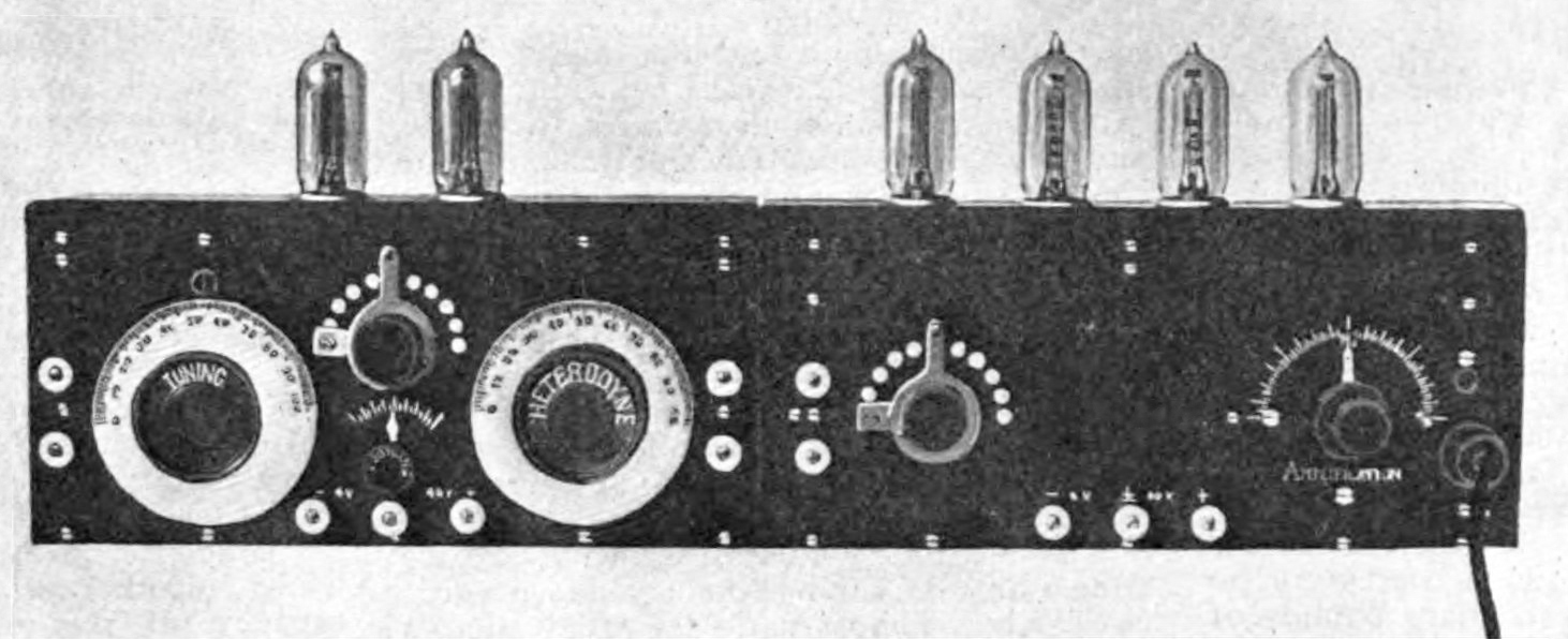
English: One of the first prototype superheterodyne radio receivers built by inventor Edwin Armstrong. The superheterodyne, the circuit used in virtually all modern radios, was invented by Armstrong in 1918 while he worked in a US Army Signal Corps laboratory in Paris during World War 1. This is one of the receivers constructed at that laboratory, shown in a 1920 article in an amateur radio magazine. It is constructed in two parts. The lefthand section consists of the mixer and local oscillator. The oscillator uses an Armstrong "tickler" circuit. The two large knobs are the input tuning capacitor (left, labeled TUNING) and the local oscillator tuning capacitor (right, labeled HETERODYNE). The upper center multiposition switch controls the filament current, while the lower center knob controls the feedback coupling of the oscillator. The righthand section contains an IF transformer filter, 3 stages of RC-coupled IF amplification and a detector stage. The multiposition switch on this section controls the filament current of the 4 tubes, while the righthand knob (labeled AMPLIFICATION) controls the gain of the amplifier. All the tubes are VT triodes made by Western Electric. The circuit uses an IF of around 75 kHz. Caption: "One of the first complete Armstrong amplifiers built in Armstrong's Paris laboratory. The cabinet at the left contains the tuning and heterodyne circuit and at the right the amplifying cabinet is shown" |
| Date | |
| Source | Retrieved January 25, 2014 from H. W. Houck, "The Armstrong Super-Autodyne Amplifier, part 1" in Radio Amateur News, Experimenter Publishing Co., New York, Vol. 1, No. 8, February 1920, p. 403 on Google Books |
| Author | H. W. Houck |
Licensing
This media file is in the public domain in the United States. This applies to U.S. works where the copyright has expired, often because its first publication occurred prior to January 1, 1929, and if not then due to lack of notice or renewal. See this page for further explanation.
|
 | |
 |
This image might not be in the public domain outside of the United States; this especially applies in the countries and areas that do not apply the rule of the shorter term for US works, such as Canada, Mainland China (not Hong Kong or Macao), Germany, Mexico, and Switzerland. The creator and year of publication are essential information and must be provided. See Wikipedia:Public domain and Wikipedia:Copyrights for more details.
|
| Annotations | This image is annotated: View the annotations at Commons |
File history
Click on a date/time to view the file as it appeared at that time.
| Date/Time | Thumbnail | Dimensions | User | Comment | |
|---|---|---|---|---|---|
| current | 17:25, 2 May 2021 | 1,462 × 596 (240 KB) | commons>Materialscientist | FFT |
File usage
There are no pages that use this file.