File:Rankine cycle layout.png
Jump to navigation
Jump to search

Size of this preview: 800 × 519 pixels. Other resolutions: 320 × 208 pixels | 640 × 415 pixels | 1,024 × 664 pixels | 1,280 × 830 pixels | 1,850 × 1,200 pixels.
Original file (1,850 × 1,200 pixels, file size: 142 KB, MIME type: image/png)
File history
Click on a date/time to view the file as it appeared at that time.
| Date/Time | Thumbnail | Dimensions | User | Comment | |
|---|---|---|---|---|---|
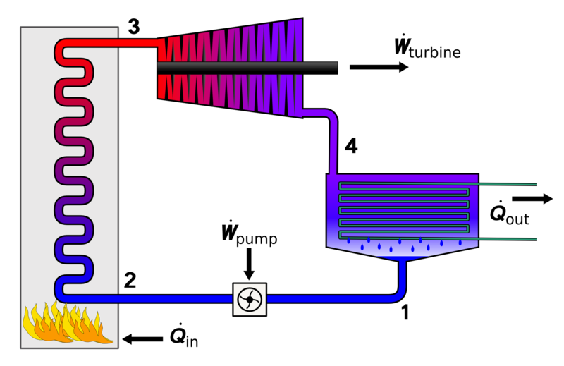
| current | 13:20, 24 June 2009 | | 1,850 × 1,200 (142 KB) | commons>Sv1xv | {{Information |Description={{en|1=Diagram showing the basic layout of a Rankine cycle; Fluid is pumped to high pressure going from state 1 to 2. Heat is added in the boiler by the burning of fuel (although heat can be added by any method) boiling the flui |
File usage
There are no pages that use this file.